


.jpg)


 (1).jpg)


.png)


.png)
.jpeg)


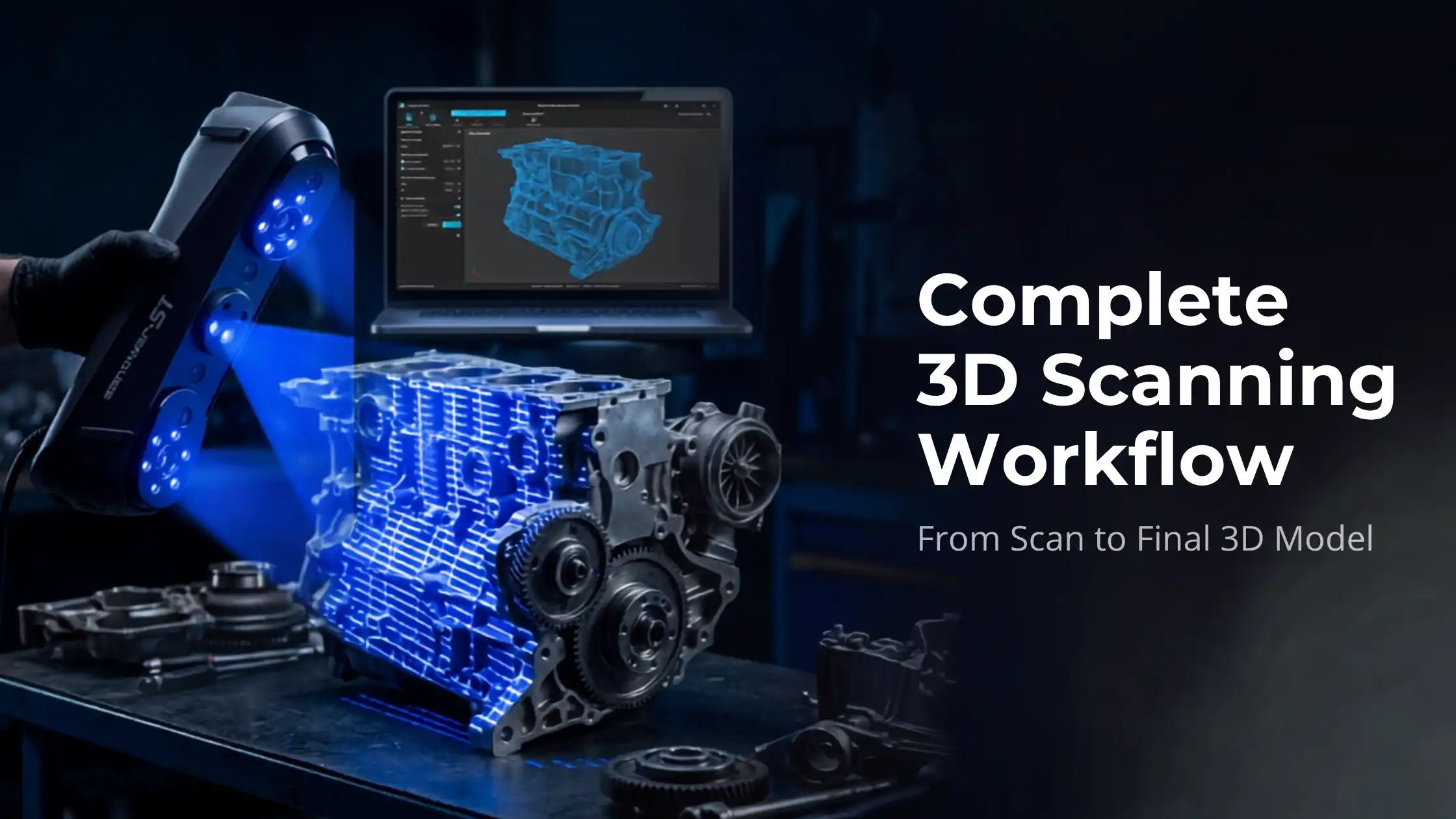
Capturing a 3D scan is the easy part. Turning that scan into a usable model, clean, watertight, and ready for printing, manufacturing, or analysis, is where most beginners get stuck. The 3D scanning workflow is the bridge between raw scan data and finished output.This guide walks through the complete process, from data capture to final export, with the tools and techniques used by professionals across industries.What Is a 3D Scanning Workflow?A 3D scanning workflow is the structured sequence of steps that converts a physical object into a digital 3D model. It includes scanning, point cloud processing, mesh generation, cleanup, alignment, and (often) CAD conversion.Skipping or rushing any step compromises the final output. A great scan with poor post-processing produces a worse model than an average scan handled well.Complete 3D Scanning Workflow Step by StepA professional 3D scanning workflow has seven distinct stages.1. Data Capture (3D Scanning)The first step is capturing the physical object using a 3D scanner. The choice of technology, structured light, laser, photogrammetry, affects accuracy, resolution, and speed.Structured light scanners are excellent for small to medium objects with high detail demandsLaser scanners handle larger objects and difficult surfaces betterPhotogrammetry uses photographs and is the lowest-cost entry pointGood capture practices: stable lighting, matte (non-reflective) surface, and adequate overlap between scan passes. Get capture right and the rest of the workflow becomes faster.2. Point Cloud ProcessingThe scanner outputs raw point cloud data, millions of XYZ coordinates describing the object’s surface. This data is dense and noisy.Point cloud processing involves:Removing background and stray pointsFiltering noiseDown-sampling for manageabilityAligning multiple scan passesTools like Geomagic, CloudCompare, and Polyworks handle this stage. Clean point clouds make every later step easier.3. Mesh GenerationThe cleaned point cloud is converted into a polygon mesh, connecting points into triangular faces that form a continuous surface. This is the point cloud to mesh conversion step.Mesh density matters. Too few polygons lose detail; too many slow every subsequent operation. Most workflows generate a high-density mesh first, then decimate to a manageable size for editing.4. Mesh Cleanup and OptimisationRaw meshes contain holes, overlapping triangles, inverted normals, and surface noise. Mesh cleanup fixes:Holes (filled either flat or with curvature continuity)Overlapping or self-intersecting geometryInverted face normalsSurface roughness from scan noiseFloating disconnected fragmentsA clean, watertight mesh is essential for 3D printing, simulation, or CAD conversion. This is one of the most time-consuming but most valuable stages of the workflow.5. Scan Alignment and MergingFor larger objects, multiple scans from different angles must be aligned and merged into a single coherent model. Most modern scanning software uses two-stage alignment:Coarse alignment, manually selecting reference points to roughly position scansFine alignment (ICP, Iterative Closest Point), automated precision alignmentGood alignment is invisible; bad alignment shows up as doubled surfaces, gaps, or step-edges. Reference markers (or “targets”) placed on the object before scanning dramatically improve alignment quality.6. CAD Conversion (When Needed)For engineering and reverse engineering applications, mesh data isn’t enough, you need parametric CAD. The scan-to-CAD conversion process recreates the geometry as solid CAD bodies using tools like Geomagic Design X, SolidWorks ScanTo3D, or Fusion 360.The two main approaches:Auto-surfacing, software fits surfaces to the mesh automatically (fast, lower precision)Feature-based reconstruction, you manually identify and recreate features like holes, fillets, and flat faces (slower, fully parametric)Engineering applications almost always require feature-based work; pure visualisation often gets by with auto-surfacing.7. Final Model ExportThe last step is exporting in the format your downstream use needs:STL, for 3D printingOBJ, for visualisation, rendering, VRSTEP / IGES, for CAD interchange and manufacturingPLY, for further mesh processing3MF, modern alternative to STL for slicersMost professional workflows export multiple formats simultaneously to cover different downstream needs.Tools and Software for the 3D Scanning WorkflowThe most-used tools at each stage:Capture: depends on the scanner, usually OEM softwarePoint cloud processing: Geomagic Wrap, CloudCompare, PolyWorksMesh generation and cleanup: Geomagic Wrap, MeshLab, Meshmixer (free, beginner-friendly)Scan to CAD: Geomagic Design X, Fusion 360, SolidWorks ScanTo3DSTL repair: Meshmixer, Materialise Magics, Microsoft 3D BuilderBeginners can do an enormous amount with the free tools, MeshLab, Meshmixer, and CloudCompare cover most casual workflows.Common Challenges in the 3D Scanning WorkflowRecurring problems and how to address them:Noise in scan data, improve scanner calibration, use matte spray on glossy surfaces, scan in stable indirect lightingHoles in the mesh, use scanning patterns with adequate overlap; fill holes intelligently in mesh softwareAlignment errors, use physical reference markers; ensure scans share at least 30% overlapResolution mismatches, match scanner settings to the object’s smallest critical featureA disciplined capture stage prevents most processing-stage headaches.How to Improve Accuracy in 3D ScanningFor the highest-fidelity results:Calibrate the scanner before every important sessionMaintain constant scanning distance (per scanner spec)Use reference markers on the objectCapture at multiple angles with generous overlapApply matte spray to reflective surfacesThese steps compound. Each one improves accuracy by a few percent; together they decide whether the final model is usable for engineering.Use Cases of the 3D Scanning WorkflowA clean 3D scanning workflow powers applications across industries:Manufacturing & quality inspection, comparing scanned parts against CAD nominalsReverse engineering, recreating CAD for legacy parts or competitor analysisHealthcare, patient-specific prosthetics, dental models, surgical planningHeritage and museums, digital archiving of irreplaceable artefactsVisual effects and gaming, high-fidelity asset captureDigital twin creation, operational replicas for monitoring and simulationThe technology is mature; the workflow discipline is what separates good outputs from great ones.Why a Structured Workflow MattersA structured workflow delivers three benefits:Repeatability. Two operators on the same scanner produce the same model.Quality control. Each stage has acceptance criteria before moving to the next.Efficiency. Less time troubleshooting the same problems repeatedly.For professional use, especially in regulated industries like aerospace, medical, or automotive, the workflow is as important as the hardware.Conclusion3D scanning is no longer just for engineers with industrial-class hardware. Modern handheld scanners and accessible software have brought professional-grade workflows within reach of designers, makers, and small manufacturers.Master the seven-stage workflow, capture, point cloud processing, mesh generation, cleanup, alignment, CAD conversion, export, and you’ll handle almost any 3D scanning project with confidence.Explore industrial-grade 3D scanners on 3idea Technology: https://www.3idea.in/products/3d-scannerThe right scanner plus a disciplined workflow unlocks one of the most powerful capabilities in modern digital manufacturing.


Free Shipping